Consider the field magnetization characteristics of a d.c. shunt generator shown in the Fig. 1.
 The critical resistance is the slope of the critical resistance line.

Now if RC is asked at speed N2, while data for O.C.C. is given at N1. It is known that,

Note : Generate the data for O.C.C. at new speed and repeat the procedure to obtain RC.
1. Drawn O.C.C. for given speed N1.
2. Draw a line tangential to this O.C.C. say OA.
3. Draw a line representing the given Rsh say OP.
4. Select any field current say point R.
5. Draw vertical line from R to intersect OA at S and OP at T.
6. Then the critical speed NC is,
 |
| Fig. 1 Concept of critical resistance |
The Fig. 1 shows that generator voltage builds in step till point A. This point is intersection of field resistance line with the open circuit characteristics (O.C.C.). The voltage corresponding to point A is the maximum voltage it can generate. If the slope of field resistance line is reduced by decreasing the field resistance, the maximum voltage generator can build will be higher than that corresponding to point A. Similarly if the slope of field resistance line is increased by increasing the field resistance, the maximum voltage generator can build will be less that that corresponding to point A i.e. corresponding to point B.
If now the slope of the field resistance line is increased in such a way that it becomes tangential to the lower part of the open circuit characteristics. The voltage corresponding to this point is EC. This voltage is just sufficient to drive the current through field resistance so that cumulative process of building the voltage starts. This value of field resistance is called critical resistance denoted as RC, of the shunt field circuit at given speed.
Note : If field circuit resistance is more than RC at start then induced e.m.f. fail to drive current through field circuit and generator fails to excite at given speed.
Similar to the critical resistance there is a concept of critical speed. We know that E α N. As speed decreases the induced e.m.f. decreases and we get O.C.C. below the O.C.C. at normal speed. If we go on reducing the speed, at a particular speed we will get O.C.C. just tangential to normal field resistance line.
Note : This speed at which the machine just excites for the given field circuit resistance is called the critical speed of a shunt generator denoted as NC.
1.1 Practical Determination of RC
Generally data for plotting the open circuit characteristics is given. Plot the characteristics on the graph paper to the scale.
Draw the tangent, to the initial part of this O.C.C. then the slope of this line is the critical resistance for the speed at which the data is given.
Note : If speed changes, then the O.C.C. changes hence the value of RC changes.Now if RC is asked at speed N2, while data for O.C.C. is given at N1. It is known that,
Note : Generate the data for O.C.C. at new speed and repeat the procedure to obtain RC.
1.2 Critical Speed
It is known that as speed changes, the open circuit characteristics also changes, similarly for different shunt field resistances, the corresponding lines are also different.
Note : The speed for which the given field resistance acts as critical resistance is called the critical speed, denoted as NC.
Thus if the line is drawn representing given Rsh then O.C.C. drawn for such a speed to which this line is tangential to the initial portion, is nothing but the critical speed NC.
Graphically critical speed can be obtained for given Rsh. The steps are,1. Drawn O.C.C. for given speed N1.
2. Draw a line tangential to this O.C.C. say OA.
3. Draw a line representing the given Rsh say OP.
4. Select any field current say point R.
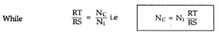
5. Draw vertical line from R to intersect OA at S and OP at T.
6. Then the critical speed NC is,

 |
| Fig. 2 Determine critical speed |
Comments
Post a Comment
Comment Policy
We’re eager to see your comment. However, Please Keep in mind that all comments are moderated manually by our human reviewers according to our comment policy, and all the links are nofollow. Using Keywords in the name field area is forbidden. Let’s enjoy a personal and evocative conversation.