The performance of the motor
is sometimes expressed in terms of comparison of various torques such
as full load torque, starting torque and maximum torque. The comparison
is obtained by finding out ratios of these torques.
sf = (Ns - N)/Ns = (250-247)/250 = 0.012 = Full load slip
sm = R2/X2 = 0.016/0.265 = 0.06037
i) TF.L./Tm = (2 sm sf )/(sm2+ sf2) = (2 x 0.06037 x 0.012)/(0.060372 + 0.0122)
ii) Tst/Tm = (2 sm )/(1 + sm2) = (2 x 0.06037)/(1 + 0.060372) = 0.1203
1.1 Full load and Maximum Torque Ratio
In general, Tα (s E22 R2)/(R22 +(s X2)2)
Let sf = Full load slip
... TF.L. α (sf E22 R2)/(R22 +(sf X2)2)
... TF.L. α (sf E22 R2)/(R22 +(sf X2)2)
and sm = Slip for maximum torque Tm
... Tm α (sm E22 R2)/(R22 +(sf X2)2)

Dividing both numerator and denominator by X22 we get,

Dividing both numerator and denominator by X22 we get,
But R2/X2 = sm
TF.L./Tm = (sf x 2 sm2)/(sm x (sm2+ sf2))
TF.L./Tm = (2 sf sm)/(sm2 + sf2)
1.1 Starting Torque and Maximum Torque Ratio
Against starting with torque equation as,
T α (s E22 R2)/(R22 +(s X2)2)
Now for Tst, s =1
Tst α (E22 R2)/(R22 +( X2)2)
Tst α (E22 R2)/(R22 +( X2)2)
While for Tm, s = sm

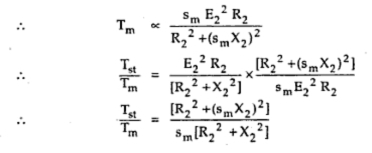
Dividing both numerator and denominator by X22 we get,

Substituting R2/X2 = sm

Infact using the same method, ratio of any two torques at two different slip values can be obtained.
Sometimes using the relation, R2 = a X2 the torque ratios are expressed interms of constant a as,
TF.L./Tm = (a sf )/(a2+ sf2)
TF.L./Tm = (a sf )/(a2+ sf2)
and Tst/Tm = 2 a/ (1 + a2)
where a = R2/X2 = sm
Example 1 :
A 24 pole, 50 Hz, star connected induction motor has rotor resistance
of 0.016 Ω per phase and rotor reactance of 0.265 Ω per phase at
standstill. It is achieving its full load torque at a speed of 247
r.p.m. Calculate the ratio of
i) Full load torque to maximum torque ii) starting torque to maximum torque
Solution : Given values are,
P = 24, f = 50 Hz, R2 = 0.016 Ω, X2 = 0.265 Ω, N = 247 r.p.m.
Ns = 120f / P = (120x50)/24 = 250 r.p.m.sf = (Ns - N)/Ns = (250-247)/250 = 0.012 = Full load slip
sm = R2/X2 = 0.016/0.265 = 0.06037
i) TF.L./Tm = (2 sm sf )/(sm2+ sf2) = (2 x 0.06037 x 0.012)/(0.060372 + 0.0122)
ii) Tst/Tm = (2 sm )/(1 + sm2) = (2 x 0.06037)/(1 + 0.060372) = 0.1203
Comments
Post a Comment
Comment Policy
We’re eager to see your comment. However, Please Keep in mind that all comments are moderated manually by our human reviewers according to our comment policy, and all the links are nofollow. Using Keywords in the name field area is forbidden. Let’s enjoy a personal and evocative conversation.