Construction of Three Phase Induction motor

Basically the induction motor consists of two main parts, namely

  1. The part i.e. three phase windings,which is stationary called stator.
  2. The part which rotates and is connected to the mechanical load through shaft called rotor.
        The conversion of  electrical power to mechanical power takes place in a rotor. Hence rotor develops a driving torque and rotates.

Stator
       The stator has a laminated type of construction made up of stampings which are 0.4 to 0.5 mm thick. The stampings are slotted in its periphery to carry the stator winding. The stampings are insulated from each other. Such a construction essentially keeps the iron losses to a minimum value. The number of stampings are stamped together to build the stator core. The built up core is then fitted in a casted or fabricated steel frame. The choice of material for the stampings is generally silicon steel, which minimises the hysteresis loss. The slots in the periphery of the stator core carries a three phase winding, connected either in star or delta. This three phase winding is called stator winding. It is wound for definite number of poles. This winding when excited by a three phase supply produces a magnetic rotating field as discussed earlier. The choice of number of poles depends on the speed of the rotating magnetic field required. The radial ducts are provided for the cooling purpose. In some cases, all the six terminals of three phase stator winding are brought out which gives flexibility to the user to connect them either in star or delta. The Fig. 1 shows a stator lamination.
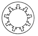
Fig.  1 Stator lamination

Rotor 
       The rotor is placed inside the stator. The rotor core is also laminated in construction and uses cast iron. It is cylindrical, with slots on its periphery. The rotor conductors or winding is placed in the rotor slots. The two typed of rotor constructions which are used for induction motors are,
  1. Squirrel cage rotor and
  2. Slip ring wound rotor 

Comments

Popular posts from this blog

Transformer multiple choice questions part 1

Hello Engineer's Q.[1] A transformer transforms (a) frequency (b) voltage (c) current (d) voltage and current Ans : D Q.[2] Which of the following is not a basic element of a transformer ? (a) core (b) primary winding (c) secondary winding (d) mutual flux. Ans : D Q.[3] In an ideal transformer, (a) windings have no resistance (b) core has no losses (c) core has infinite permeability (d) all of the above. Ans : D Q.[4] The main purpose of using core in a transformer is to (a) decrease iron losses (b) prevent eddy current loss (c) eliminate magnetic hysteresis (d) decrease reluctance of the common magnetic circuit. Ans :D Q.[5] Transformer cores are laminated in order to (a) simplify its construction (b) minimize eddy current loss (c) reduce cost (d) reduce hysteresis loss. Ans : B Q.[6] A transformer having 1000 primary turns is connected to a 250-V a.c. supply. For a secondary voltage of 400 V, the number of secondary turns should be (a) 1600 (b) 250 (c) 400 (d) 1250 A

Condition for Maximum Power Developed In Synchronous Motor

The value of δ for which the mechanical power developed is maximum can be obtained as, Note : Thus when R a is negligible, θ = 90 o for maximum power developed. The corresponding torque is called pull out torque. 1.1 The Value of Maximum Power Developed        The value of maximum power developed can be obtained by substituting θ = δ in the equation of P m .        When R a is negligible,     θ = 90 o  and cos (θ) = 0 hence, . . .               R a = Z s cosθ   and X s = Z s sinθ        Substituting   cosθ = R a /Z s in equation (6b) we get,         Solving the above quadratic in E b we get,        As E b is completely dependent on excitation, the equation (8) gives the excitation limits for any load for a synchronous motor. If the excitation exceeds this limit, the motor falls out of step. 1.2 Condition for Excitation When Motor Develops ( P m ) R max        Let us find excitation condition for maximum power developed. The excitation

Effect of Slip on Rotor Parameters : Part2

Effect of Slip on Rotor Parameters 2. Effect of Slip on Magnitude of Rotor Induced E.M.F        We have seen that when rotor is standstill, s  = 1, relative speed is maximum and maximum e.m.f. gets induced in the rotor. Let this e.m.f. be,                 E 2 = Rotor induced e.m.f. per phase on standstill condition         As rotor gains speed, the relative speed between rotor and rotating magnetic field decreases and hence induced e.m.f. in rotor also decreases as it is proportional to the relative speed N s - N. Let this e.m.f. be,                E 2r = Rotor induced e.m.f. per phase in running condition  Now        E 2r α N s while E 2r α N s - N        Dividing the two proportionality equations,               E 2r /E 2 = ( N s - N)/N s    but (N s - N)/N = slip s               E 2r /E 2 = s               E 2r = s E 2        The magnitude of the induced e.m.f in the rotor also reduces by slip times the