
Concepts of Slip Rings and Brush Assembly In Three Phase Induction Motor

Whenever there is a need of connecting the rotating member of the machine to the stationary external circuit, then slip rings and brush assembly is used.
       Consider a three phase rotating star connected winding as shown in the Fig. 1. It is required to connect external three stationary star connected resistances to this windings. The winding must keep on rotating and external resistance must remain stationary and still there should be contact between the two. This is possible by slip rings and brushes.

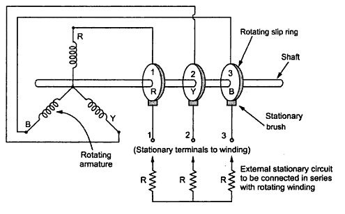
Fig.  1 Concept of slip rings and brush
       The three rings made up of conducting material called slip rings are mounted on the same shaft with which winding is rotating. Each terminal of winding is connected to an individual slip ring, permanently. Thus three ends R-Y-B of winding are available at the three rotating slip rings. The three brushes are then used. Each brush is resting on the corresponding slip ring, making contact with the slip ring but the brushes are stationary. So rotating three ends R-Y-B are now available at the brushes which are stationary as shown in the Fig. 1. Now stationary external circuit can be connected to the brushes which are nothing but the three ends of the winding.
       Thus the external stationary circuit can be connected to the rotating internal part of the machine with the help of slip rings and brush assembly. Not only the external circuit can be connected but the voltage also can be injected to the rotating winding, by connecting stationary supply to the brushes externally.

Key point : Such slip rings and brush assembly plays an important role in the working of slip ring induction motor.

Comments

Popular posts from this blog

Demagnetising and Cross Magnetizing Conductors

The conductors which are responsible for producing demagnetizing and distortion effects are shown in the Fig.1. Fig. 1        The brushes are lying along the new position of MNA which is at angle θ  from GNA. The conductors in the region AOC = BOD = 2θ  at the top and bottom of the armature are carrying current in such a direction as to send the flux in armature from right to left. Thus these conductors are in direct opposition to main field and called demagnetizing armature conductors.         The remaining armature conductors which are lying in the region AOD and BOC carry current in such a direction as to send the flux pointing vertically downwards i.e. at right angles to the main field flux. Hence these conductors are called cross magnetizing armature conductors which will cause distortion in main field flux.        These conductors are shown in the Fig. 2 Fig. 2  ...

Armature Voltage Control Method or Rheostatic Control of dc motor

Speed Control of D.C. Shunt Motor (Part2)  2. Armature Voltage Control Method or Rheostatic Control        The speed is directly proportional to the voltage applied across the armature. As the supply voltage is normally constant, the voltage across the armature can be controlled by adding a variable resistance in series with the armature as shown in the Fig. 1. Fig. 1 Rheostat control of shunt motor        The field winding is excited by the normal voltage hence I sh is rated and constant in this method. Initially the reheostat position is minimum and rated voltage gets applied across the armature. So speed is also rated. For a given load, armature current is fixed. So when extra resistance is added in the armature circuit, I a remains same and there is voltage drop across the resistance added ( I a R). Hence voltage across the armature decreases, decreasing the speed below normal value. By varyi...

Characteristics of Separately Excited D.C. Generators

The characteristics is separately excited d.c. generator are divided into two types, 1) Magnetization   and         2) Load characteristics. 1.1 Magnetization or Open Circuit Characteristics         The arrangement to obtain this characteristics is shown in the Fig. 1. Fig. 1  Obtaining O.C.C. of separately excited generator        The rheostat as a potential driver is used to control the field current and the flux. It is varied from zero and is measured on ammeter connected.        E o  = (ΦPNZ) / (60A)        As I f is varied, then Φ change and hence induced e.m.f. E o  also varies. It is measured on voltmeter connected across armature. No Load is connected to machine, hence characteristics are also called no load characteristics which is graph of E o  against field current I f as sho...