i) Torque - Armature current characteristics
From the speed equation we get,
N α (V - Ia Ra)/Φ
αV - Ia Ra as Φ is constant
So as load increases, the armature current increases and hence drop Ia Ra also increases.
So the characteristics is slightly droping as shown in the Fig. 2.
But for all practical purposes these type of motors are considered to be a constant speed motors.
iii) Speed - Torque characteristics
For a d.c. motor T α Φ Ia
For a constant values of Rsh and supply voltage V, Ish is also constant and hence flux is also constant.
... Ta α Φ Ia
... Ta α Φ Ia
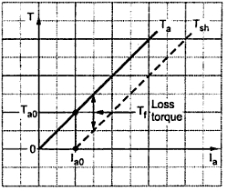
The equation represents a straight line, passing through the origin, as shown in the Fig. 1. Torque increases linearly with armature current. It is seen earlier that armature current is decided by the load. So as load increases, armature current increases, increasing the torque developed linearly.
 |
| Fig. 1 T Vs Ia for shunt motor |
Now if shaft torque is plotted against armature current, it is known that shaft torque is less than the armature torque and the difference between the two is loss torque Tf as shown. On no load Tsh = 0 but armature torque is present which is just enough to overcome stray losses shown as Ta0. The current required is Ia0 on no load to produce Ta0 and hence Tsh graph has an intercept of Ia0 on the current axis.
To generate high starting torque, this type of motor requires a large value of armature current at start. This may damage the motor hence d.c. shunt motors can develop moderate starting torque and hence suitable for such applications where starting torque requirement is moderate.
ii) Speed - Armature current characteristics From the speed equation we get,
N α (V - Ia Ra)/Φ
αV - Ia Ra as Φ is constant
So as load increases, the armature current increases and hence drop Ia Ra also increases.
Hence for constant supply voltage, V - Ia Ra decreases and hence speed reduces. But as Ra is very small, for change in Ia from no load to full load, drop Ia Ra is very small and hence drop in speed is also not significant from no load to full load.
 |
| Fig. 2 N Vs Ia for shunt motor |
But for all practical purposes these type of motors are considered to be a constant speed motors.
iii) Speed - Torque characteristics
These characteristics can be derived from the above two characteristics. This graph is similar to speed-armature current characteristics as torque is proportional to the armature current. This curve shows that the speed almost remains constant through torque changes from no load to full load conditions. This is shown in the Fig. 3.
 |
| Fig. 3 N Vs T for shunt motor |
Comments
Post a Comment
Comment Policy
We’re eager to see your comment. However, Please Keep in mind that all comments are moderated manually by our human reviewers according to our comment policy, and all the links are nofollow. Using Keywords in the name field area is forbidden. Let’s enjoy a personal and evocative conversation.