Now we will consider the definitions of different types of winding pitches, required in the design of the armature winding.
1.1 Back Pitch
The distance which is measured interns of armature conductors i.e. between top and bottom coil sides of a coil measured around the back of the armature i.e. away from the commutator is called back pitch and is denoted by . It is measured interms of coil sides.
Note : Since it is difference between odd and even number, it is always odd number.
The size of the coil is decided by the back pitch. The back pitch is normally equal to coilsides per pole. It is shown for lap and wave type of winding in the Fig. 1.
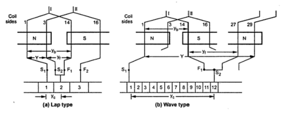 |
| Fig. 1 |
The back pitch for the winding shown in the Fig. 1 is yb = 14 - 1 = 13 as coilsides 1and 14 are of coil number 1.
1.2 Front Pitch
It is defined as the distance measured between two coilsides which are connected to some commutator segment. It is denoted by yf. The front pitch for the winding shown in the Fig. 1 is yf = 14 - 3 = 11. This is front pitch for lap winding while for wave winding yf = 27 - 14 = 13. The front pitch for both lap and wave type winding is odd. If for a lap winding the connections are traced then the movement is backwards (coil side 14 to coil side 3). Hence the type of winding can be determined from front pitch and it does not affect the size of coils.
1.3 Winding Pitch
It is defined as the distance between the starts of two consecutive coils measured in terms of coil sides. It is denoted by Y.
For lap winding, Y = yb - yf
For Wave winding, Y = yb + yf
For the lap winding shown in the Fig. 1 the winding pitch is Y = 13 - 11 = 2 while for wave winding Y = 13 + 13 = 26. It is also the distance round the armature between two consecutive conductors. Practically, coil pitches or winding pitches as low as eight tenths of a pole pitch are employed without much reduction in emf.
Note : Fractional pitches windings are intentionally used so as to achieve saving in copper of the end connections and for improvement in commutation.
1.4 Commutator Pitch
It is defined as the distance between the two commutator segments to which the two ends i.e. starts and finish of a coil are connected. It is measured in terms of commutator segments and it is denoted by yc. For the windings shown in the Fig. 1.
yc = 2 - 1 = 1 for simplex lap winding
yc= 12 - 1 = 11 for simplex wave winding
For lap winding is the difference between yb and yf while for wave winding yc is the sum of yb and yf. The number of bars between the coil leads is commutator pitch. In general yc is the 'plex' of lap wound armature. It is 1, 2, 3 for simplex, duplex, triplex lap windings respectively.
On tracing through simplex lap winding,a segment adjacent to the first one is reached after traversing through one coil. For simplex wave winding, the adjacent segment is reached after traversing through P/2 coils.
Comments
Post a Comment
Comment Policy
We’re eager to see your comment. However, Please Keep in mind that all comments are moderated manually by our human reviewers according to our comment policy, and all the links are nofollow. Using Keywords in the name field area is forbidden. Let’s enjoy a personal and evocative conversation.