This allows two circuits that are electrically isolated from each other to interact. The current in the first circuit creates a magnetic field around it, which, acting on the second circuit and transferring its energy to it, creates a current in it. This article will show you how to test a transformer.
Visually Verify Transformer.
Often the cause of the failure of the transformer is the overheating of its internal winding. If the transformer housing is swollen or shows burn marks, please do not check it further.
Identify the winding of the transformer. It was expected to have easily readable labels. However, it is often helpful to have a circuit diagram containing your transformer to find out how it is related. The circuit diagram can be found on the product documentation or on the manufacturer's website. Which could be identified in 4 ways:
1# Identify the Input and Output of the Transformer
The first electrical circuit to produce a magnetic field is connected to its primary winding. The voltage applied to this winding must be shown on the transformer itself and can be found on the diagram. The second circuit, which derives the energy from the magnetic field, is connected to the secondary winding of the transformer. The voltage produced in this circuit should also be indicated on the transformer itself.
2# Identify Filtration at the Outlet
Condensers and diodes are often attached to the secondary winding of a transformer to convert variable power to constant output power. This filtering and waveform shift is not expressed in the label of the transformer. They must be seen in the attached diagram.
3# Identify Input of the Transformer
Link the source with the input circuit. Measure the voltage through the primary winding by using a tester in AC (alternating current) mode. Either the primary circuit or the transformer can be defective if it is more than 80 percent lower than anticipated. Disconnect the primary winding from the input circuit, in this case. If, after that, the input voltage (but not the disconnected primary winding) increases to the intended value, then the transformer 's primary winding is defective. The fault is not in the transformer, but in the input circuit if the voltage has not increased.
4# Measure Voltage at the Transformer 's Output
Use the AC tester mode if you have decided that the output is not filtered or converted from the secondary one. Switch the tester to DC mode if there's filtering and signal conversion. Either the transformer or the signal filtering and conversion unit would be affected if the tester does not display the expected output voltage. Separately, check all of the components of this block. If they are all in place, then the transformer is defective.
How to Check a Transformer with a Multimeter?
Checking the windings of the transformers can easily trigger panic in the beginner, having a bunch of leads coming from various windings is hard to find out where to start such a check.
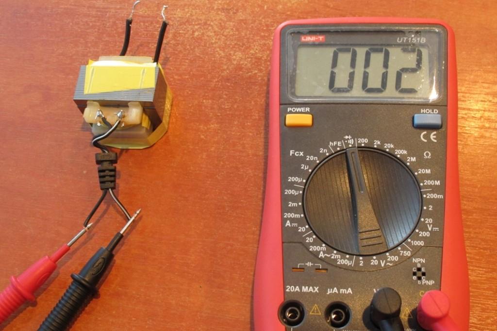
First of all, you need to deal with a simpler example and grasp the very concept of how to inspect a transformer with a multimeter. Today we're going to show you how to test a 220V to 12V step-down transformer with a multimeter in two phases.
Our basic charger transformer has only four terminals, i.e. two secondary winding wires and two main ones. The whole process of testing the transformer with a multimeter is to verify the integrity of the windings. First, you need to switch the multimeter to the diode test or resistance measurement mode. Then one of the windings is tested, the polarity of the relation of the probes doesn't matter.
And if the issue occurs unexpectedly, how do you decide the windings of the transformer? It can be addressed by the fact that the resistance of the primary winding at the step-down transformer is often higher.
A winding that has a split doesn't ring at all. If there is a need to check the transformers that have several lines of primary winding and several secondary windings, each winding of such a transformer is tested separately.
This method of testing the transformer with a multimeter is very simple and helps to determine the integrity of the winding.

Troubleshooting Transformers
Investigating Replaced Transformer
If a newly bought transformer is likely to damage from elsewhere in one of the circuits. It has a higher chance that those transformer circuits are more likely to burnout due to short circuiting.
When we replace the new transformer with the old one, we really have to make sure it never happens again. Additional checks are likely to be carried out if any damage is detected.
In the case of transformer overloading circuits, the resulting overheating of the core is more likely to burn. Main power connexions should be cut off to further prevent damage to the entire transformer.
Isolate Transformer from Input and Output to Find Cause of Failure
This phase is known to be the best method for identifying the root cause of major failure. A linear fuse would only have a single source input and output. This is the best way to evaluate whether the problem emerged from the input or output circuit.
For complex removal of inputs as well as transformer outputs, removing one by one to find out which causes this failure is the main component of the overall entire circuit.
Author’s name: Kiran Daware
Company Name: Nicore India Pvt. Ltd.
Website: https://nicoreindia.com/
Bio: Kiran Daware is the junior electrical engineer at Nicore India Pvt. Ltd. He is into development team of silicon steel magnetic core. He is also a technical writer at Nicore India where he owns blog a electricaleasy.
Hi nice ARTICLE
ReplyDelete